The RFWEL Forums are now archived. All threads and discussions are preserved here for reference. New posts, replies, and comments are no longer accepted. For support or enquiries, please visit our Knowledge Base or Contact Us.
Venstar T7850- Addition of Common Wire
This thread is part of the RFWEL Forums Archive. It is preserved here for reference and is no longer open for new replies or comments.
⌕
Pageof 1‹›⌗ Filter ▾
N
Nicola
New Member
Join Date: Nov 2020
Posts: 1
11-16-2020, 03:46 PM
#1
I recently acquired Venstar T7850 Programmable WiFi Thermostat ( https://shop.rfwel.com/venstar-t7850...hermostat.html) to replace my old thermostat. However, I just learned that the thermostat requires the use of a common wire for it to power on the digital display. Any advice on an easy way to do this will be highly appreciated.
Tags: None
L
Lameck
Wireless Guru
Join Date: Apr 2020
Posts: 65
11-17-2020, 01:37 PM
#2
It is important to note that taking a picture of the original wiring of the old thermostat will work as a reference to aid recall what terminal each thermostat wire was connected to.
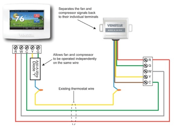
A wire can be added by the installation of the ACC0410 Add-A-Wire accessory. With this one can be able to control two thermostat signals from one control wire. Move the green wire from the G terminal to the C terminal on the thermostat and at the heating and cooling equipment. Carry the Add-A-Wire signal using the yellow wire. The wiring is as illustrated below. This can be as well applied to other Venstar models where additional wiring cannot be run
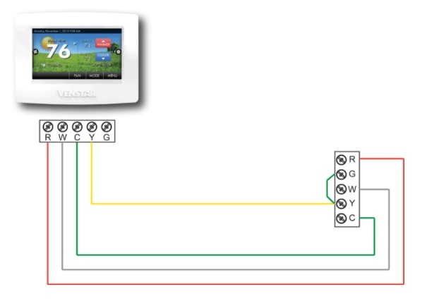
Another option is to sacrifice independent control of your indoor fan. To do this, please adhere to the procedure below.
1\. Disconnect power from your heating and/or cooling system to prevent damage to the equipment's fuse or the transformer.
2\. Move the wire connected to the G terminal which controls your indoor fan to the C terminal (common) on the thermostat.
3\. At the heating and cooling equipment repeat the same step and move the G terminal wire to the C terminal.
4\. At the heating and cooling equipment place a jumper wire from the Y equipment terminal to the G equipment terminal. With this, the fan will turn on when the thermostat calls for cooling or heating but it will not give you independent fan control from the thermostat.
Refer to the diagram below for wiring instructions